Creating a Numeric Control to Command Objects
Scenario: You want to create a graphic or symbol that allows you to commands the Present Value with a Numeric command control.
There are two methods of doing this:
- You can gather object type information for a data point and then draw and configure a customized command symbol or graphical element, such as a button, that allows you to send commands from within a graphic.
- You can drag-and-drop an existing default command symbol from a project library to a graphic. To add a default command symbol from a project library, proceed directly to Designating and Adding Default Command Symbol to a Graphic.
Reference:
- For overall background information, see Command Control Configuration.
- For Command Control and Navigation properties background information, see Command Control Properties and Command and Navigation Properties.
- For symbols background support when creating command control symbols, see Symbol Property Substitution.
Workflow diagram:
Prerequisites:
- You have reviewed or completed Preparing to Create Controls to Command Objects.
- System Manager is in Engineering mode.
Steps:
To draw and configure the Numeric command control, complete the procedures in order.
The following is just one way to o draw and configure the Numeric, String, or Password command controls to command from within a graphic.
- To create a new command control element on your graphic, from the File menu, select New Graphic
 .
.
- Click Command Control
 , and draw a rectangular shape on the canvas.
- The undefined element displays on the canvas.
- From the Property View (Command Control Properties), expand the Command Control properties, and from the Control Type drop-down menu, select Numeric.
0.00displays in the command control element.
- In the Parameter Name field, type the data point’s Parameter name obtained from the Models & Functions Command Configuration table. This field is case–sensitive. This property will be the same Parameter property later defined in the Command and Navigation section for each control.
- For this example, type: Value.
- To configure the command control properties, do the following:
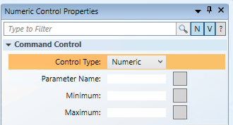
- Minimum: Enter the minimum value the Command Control is allowed to display.
- Maximum: Enter the maximum value the Command Control is allowed to display.
The following instructions are just one example of how a Numeric command control can be drawn or configured to issue a command from within a graphic.
Scenario: You want to create a Numeric command control that allows you to command the Present Value property of an Analog Value data point from within a graphic.

NOTE:
If you create a command control element in a symbol instead of on a graphic, follow the steps below, replacing the Target and any other hard-coded references with * substitutions in the Evaluation Editor. For more information, see Symbol Property Substitution.
- You have reviewed the Command and Navigation properties section and have a full understanding of the fields and the options available to you for configuring the Command and Navigation Properties.
- You have drawn and configured a numeric command control on the graphic and you have completed the steps in the Gathering Data Point Command information section.
- Select the Numeric command control on the canvas, and from the Property View expand the Command and Navigation properties.
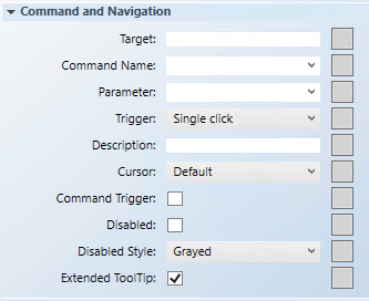
- In the Target field, drag-and-drop a designated data point from System Browser. If the target designation does not contain a property, the default property is targeted. Otherwise you must specify the property by typing a period (.) and then the property name after you drag-and-drop the data point into the Target field, for example:
CCProject.LogicalView:Logical.PXRack.B.Block.Hcrv;.Property_Name.
- For this example: Drag-and-drop an Analog Output data point into the Target field. It is not necessary to type [.Present_Value] at the end of the path as it is the default property used. NOTE: If you have the data point selected in System Browser, or you have selected a symbol instance of the data point on the canvas, the data point information is displayed in the Operations and Extended Operations tab, from there, drag-and-drop the property you want to target into the Target field. The property name is added automatically.
- From the Command Name drop-down menu, select or type the command rule that you want to apply to the property.
- For this example, type or select Write.
NOTE; The Command Name must match the Name of the command in the Models and Functions Command Configuration section. This field is case-sensitive.
- In the Parameter field, do one of the following:
- Select the value from the drop-down menu.
NOTE: For a stand-alone command control, if you have multiple parameters, only one parameter receives the value from the control itself and all other parameter values must be hard-coded.
- For this example, delete everything but the parameter name, which in this case is: Value
- For Numeric controls, commands are sent by pressing ENTER.
NOTE: The Trigger drop-down menu is irrelevant for this control.
- (Optional) In the Description field, type a brief description of the command that will display in the tooltip.
- From the Cursor drop-down menu, select the cursor preference that you want to display when the command is active.
- Select the Command Trigger check box to enable the command control to initiate and send a command.
- To disable the command control, select the Disabled check box, and from the Disabled Style dropdown menu, select how the disabled command control displays when disabled.
- For example, if the selected data point is
Out_of_Serviceand the command is disabled, the Disabled Style will be active at runtime to reflect this.
- Checked by default, the Extended Tooltip check box displays the following command object details: Target, Command Name, and Parameter. If enabled, the extended tooltip is added to any existing tooltips configured for the element.
- Click Save As
 .
.
Scenario: You have created a numeric command control, and you want to format the control properties:
- To format the command control Text properties, do the following:
- Font Family: From the drop-down menu, select a font to determine the command control text font. The default Font Family is Arial.
- Font Size: Type a number to determine the font size. Default Font Size is 14.
- Precision: Use the UP and DOWN buttons to determine the number of decimal places that display when the value is rounded. The default is blank.
- To format the command control Colors properties, do the following:
- Background: Type the name of a color for the background.
- Fill: Type the name of a color for the command control outline.
- Stroke: Type a name of a color for the command control characters.
- Click Save As .
- If you created a symbol and you want to designate it as the default command symbol for an object type proceed to Designating and Adding Default Command Symbol to a Graphic.