Property Evaluations
Evaluations are expressions and conditions applied to element or symbol property values to determine how an element or symbol behaves in a graphic. Property evaluations are the basis for creating animated graphics that automatically update to show a graphical representation of real time conditions of your system or facility.
There are five types of evaluations you can apply to an expression: Simple, Linear, Discrete, Animated, and Multi. The type of animation or conditions required for your graphic will determine which evaluation type to use. Evaluations and expressions are configured in the Evaluation Editor view.
Expressions
The expression can be either a direct reference to a data point name or a literal (of type Boolean, number or string).
An expression consists of a data point reference or value followed by an optional operator with another data point or value. The result of an evaluation to a property value, for example, can determine which image or symbol instance to display or what color to apply to an element depending on the value of a property.
Every property evaluation stems from the result of an expression that is used to determine how an image displays according to property values, expressions, and conditions.
Expressions consist of a data point reference, for example, an object name or value followed by an optional operator with a second data point or value. This allows you to have simple comparisons or calculations as well as use constant literals.
There are four types of expressions you can enter:
Reference
Function
object model
Script
Syntax and Conditions
Expressions in the Evaluation Editor adhere to specific syntax and consist of data point references, such as an object name or object address, or one of three literal value types: Boolean, double, and string. Conditions are applied to Linear, Discrete, and Multi evaluations.
Text Group References
In addition to using the Brush Editor or referencing a hexadecimal color code such as FFFF0000 (red) to determine the color for a property evaluation, you can also reference a color from an existing Text Group table. When the color reference is separated by a period as follows: [TextGroupName].[Value], the color associated with that value displays.
Multi Editing
You can simultaneously update multiple elements whose matching properties have evaluations applied to them. If an element in a group of elements does not have a matching property with the other elements in the group, the element is ignored and not included in the evaluation. If the same property for multiple elements have different values applied to them, those properties display with a blue background and a new value can be entered that will be applied to all the elements that share the property.
In Desigo CC 2.0, two syntax changes were made that affect object references. See the table below for the changes:
Object Reference Syntax Changes from Version 1.1 to Version 2.0 | ||
Old Syntax | Desigo CC 1.1 Example | Desigo CC 2.0 Example |
"::" replaced with ";" | MySystem.MyView:MyTree.MyNode:: MySystem.MyView:MyTree.MyNode::.Present_Value | MySystem.MyView:MyTree.MyNode; MySystem.MyView:MyTree.MyNode;.Present_Value |
"!!" replaced with "@" | MySystem.MyView:MyTree.MyNode::.!!CMD In this example, CMD represents a command. | MySystem.MyView:MyTree.MyNode;@CMD |
There are five evaluation types you can apply to an element or Symbol property in the Graphics Editor.
Simple
Simple evaluations are the most basic type of property evaluation. Simple evaluations allow you to specify a one-to-one substitution or behavior for the expression result of the property, without setting any conditions.
Simple evaluations only require you select a property and enter an expression.
Animated
The Animated evaluation is used to change a property value by setting a value for each frame and then setting the interval times between frames and their associated values. In the Animated evaluation each value condition is considered a frame. One frame is used as the Off frame.
Linear
Linear allows you to broaden the range of the expression by mapping the expression result to a minimum and maximum range. The minimum and maximum values are set to the original expression range or you can manually enter a range. A range condition can be another literal value or a symbol from the symbol library. You can have multiple range conditions for each property expression. If a minimum or maximum range is blank, the value is taken from the expression range.
Discrete
Discrete evaluations allow you to map the expression result to one or more conditions. However, unlike the Linear evaluation, the conditions of the expression are evaluated and processed in order of priority from top-to-bottom in the Evaluation Editor view. The value of the first true condition is applied and all other conditions are not used.
You can use the Discrete’s And condition to compare individual bits of an analog data point expression. The And condition uses binary encoding to compare a hexadecimal value with the binary equivalent to see whether a condition is true. For example, the hexadecimal number 2A is equivalent to the binary value of 0010 1010, and the decimal value of 42. For any bit conditions that match the bit places of 2, 4, and 6 being OR or 1, the condition is true.
Multi
Multi evaluations allow you to create evaluations for digital data points. Every possible combination of digital data point states can have results which you can set or limit in your evaluation. The Tri-State check box allows you to manage the number of required conditions for your evaluation.
Each evaluation type requires specific input and syntax for the Condition field.
Linear
Valid syntax and input include double or integer values. The Condition field can also be left blank, in which case the expression range is used.
Discrete
The following table shows examples of valid syntax for the Condition fields associated with Discrete evaluations.
Condition Example | Condition is ... |
|---|---|
12.34 | Double literal NOTE: It recommended that you use a range for the condition. |
12 | Name reference. |
<5 | Condition is smaller than 5. |
<=5 | Condition is smaller than or equal to 5. |
>5 | Condition is greater than 5. |
>=5 | Condition is greater than or equal to 5. |
..5 | True, if equal to or less than 5. |
5.. | True, if equal to or greater than 5. |
12.34..56 | True, if value is equal to or between12.34 and 56 |
.. | Always true. This is the same as a blank field. |
| Always true. |
25; 50; 75 | True if value is 25, or 50, or 75. |
&2A | True, if the (zero-based) bits 1, 3, and 5 are true. |
&4 | True, if the (zero-based) bit 2 is true. |
&0002 | True, if the (zero-based) bit 1 is true. |
Multi
In this evaluation type, every condition has a check box that is associated with an expression created for the evaluation. If you have four expressions, each condition will display four check boxes. Each check box indicates if the expression is true, false, or unspecified (ignored) for the particular condition. The condition applied is then determined by how the associated check boxes are marked and the conditions are met. For each condition, the related expression check boxes from the top section of the Evaluation Editor are ordered from left (first expression) to right (last expression).
The check box states are represented as follows:
- Checked = condition is true.
- Unchecked = condition is false.
- Green Fill = condition is neither true nor false (unspecified) and the corresponding expression is ignored.
The example condition is true if:
-Expression 1 is true or false (that is, this expression is ignored AND
-Expression 2 is true AND
-Expression 3 is false.
If an expression is not digital, the result is false if the expression result is:
- 0 for integer, double, or any other analog types
- Empty string or “0” for string types.
The Evaluation Editor's Expression field allows you to enter information whose resulting value is applied to the associated element property. In Runtime mode, the result of the value that is applied to the element evaluation displays in the Results field. The result of the Expression field is also used in creating evaluations with conditions.
The information entered into the Expression field can be a value, a string literal, one or more data point references, or a JavaScript expression, whose value or result is applied to the element property evaluation.
The information or objects accepted in the Expression field are:
- A literal (string, analog value, or True\False)
- One or more data point references
- Combination of a literal and a data point reference, separated by a question mark (?)
- A multi-line JavaScript expression
Data Point References in the Expression field
All data points are associated to a Function, and some data points are also associated with object models. When the information in the Expression field is a data point reference, you can choose one of the following result types from the Type field, in order to obtain the desired result. Depending on your selection the results are as follows:
- Reference - The expression result is the COV value of the referenced data point.
- Function - The expression result is the Function name of the referenced data point.
- Object Model - The expression result is the object model name of the referenced data point.
- Script - The expression result is the result of the JavaScript.
Working with Expression Results
You can use the Result value in conjunction with the Condition field to create evaluations.
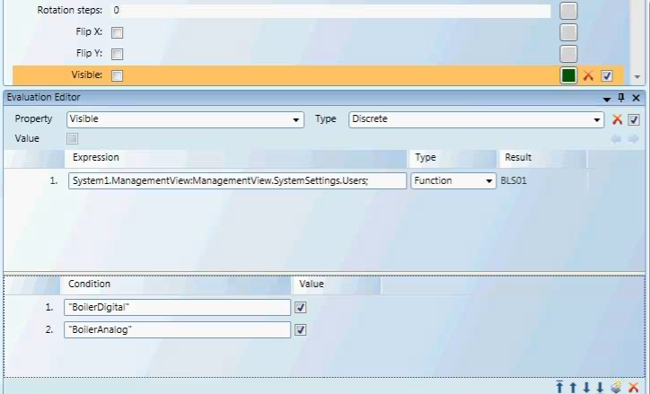
For example, If you have an element in a symbol that is invisible (the Visible property is deselected) by default, you can create a Discrete evaluation that allows the element to be visible under certain circumstances.
In this evaluation, the Expression field contains the data point, and the Function Type filter is applied. The Discrete evaluation states that if the condition of the data point is of the Function BoilerDigital or BoilerAnalog, then the value (property) is visible.
Working with a Function Type
When you select Function, from the Type field, you can then use the actual Function name in the Condition field to create evaluations. All strings must be encased in quotation marks, for example:
Fan1ST - "Fan1ST"
The Function type filters allows you to obtain a data points Function name in a graphic template, for example, and hide or display graphic elements.
This table provides a list of data point property names as they appear in the Operations tab as well as how they are displayed as variables in expressions.
Examples:
- To see an Analog Point’s defined High Limit:
. . . Local_IO.SBT_BLDG_950_AH01_RAH::.High_Limit- To see an Analog Point’s defined Low Limit:
. . . Local_IO.SBT_BLDG_950_AH01_RAH::.Low_Limit- To see the data point’s current BACnet command priority:
. . . Local_IO.SBT_BLDG_950_AH01_RAH::.Current_Priority- To see the data point’s Engineering Units:
. . . Local_IO.SBT_BLDG_950_AH01_RAH::.Units
Table of Data Property Names
Property Names | |
Name in Operations Pane | Property Variable Name |
Acknowledged Transitions | .Acked_Transitions |
Alarm Fault | .Alarm_Fault |
Alarm OffNormal (called "Fault") | .Alarm_OffNormal |
Alarm Value (called "OffNormal") | .Alarm_Value |
Change of State Count | .Change_Of_State_Count |
Change of State Time | .Change_Of_State_Time |
COV Increment | .COV_Increment |
Current Priority | .Current_Priority |
Deadband | .Deadband |
Description | .Description |
Device Type | .Device_Type |
Elapsed Active Time . | Elapsed_Active_Time |
Event Enable | .Event_Enable |
Event State | . Event_State |
High Limit | .High_Limit |
Limit Enable | .Limit_Enable |
Low Limit | .Low_Limit |
Max Present Value | .Max_Pres_Value |
Min Present Value | .Min_Pres_Value |
Notification Class | .Notification_Class |
Notify Type | .Notify_Type |
Object Identifier . | Object_Identifier |
Object Name | .Object_Name |
Object Type | .Object_Type |
Operating Status | .Operating_Status |
Out of Service | .Out_Of_Service |
Polarity | .Polarity |
Present Value | .Present_Value |
Priority Array | .Priority_Array |
Reliability | .Reliability |
Relinquish Default | .Relinquish_Default |
Resolution | .Resolution |
Status Flags | .Status_Flags |
Time Delay | .Time_Delay |
To OffNormal/To Fault/To Normal | .Event_Time_Stamps |
Units | .Units |
Inactive Text | .Inactive_Text |
Minimum Off Time | .Minimum_Off_Time |
Minimum On Time | .Minimum_On_Time |
Time of Active Time Reset | .Time_Of_Active_Time_Reset |
Time of State Count Reset | .Time_Of_State_Count_Reset |
An understanding of binary encoding may help when working with evaluations and conditions that use bitstrings.
Analog data points use a range of values to represent a condition which has more than two states, for example, the temperature data point or damper position. A computer uses binary digits, consisting of 1’s and 0’s, to read and represent those values. A “1” usually represents an On state, and “0” represents Off. To simplify the binary coding for the user, hexadecimal numbers are used to map the binary numbers into more legible values. See the Table: Binary, Decimal, and Hexadecimal equivalents.
Binary and Hexadecimal Weights
Binary numbers are based on two because it consists of a combination of the digits 0 and 1. Because a base of 2 is used in binary notation, the second place from the right has a weight of 2 because it is 2 raised to the power of 1. Hexadecimal notation is based on 16 because it is based on 16 digits.
About Hexadecimal’s
The hexadecimal notation is based on 16 digits and uses the digits 0-9 and then the letters A-F to represent the digits 10-15. Hexadecimal numbers are often preceded by Ox or followed by h.
A hexadecimal number consists of two values; each value represents one of two nibbles. A nibble is a byte (8 bits) that has been separated into two nibbles, each consisting of 4 bits.
- The lowest value for a nibble with each bit turned off is: 0000, which equals a value of 0.
- The highest value for a nibble with each bit turned on is: 1111, which equals a value of 15(1).
Converting a Hexadecimal to a Binary
To convert a hexadecimal to a binary number, use the table. For example, in order to convert the hexadecimal number 2A to binary do the following:
- Locate the hexadecimal value 2 and note the binary equivalent. The binary value for 2 is 0010.
- Locate the hexadecimal value A and note the binary equivalent. The binary value for A is 1010.
Therefore, the binary value for the hexadecimal number 2A is equivalent to: 0010 1010.
Binary, Decimal and Hexadecimal Equivalents | |||||
Binary | Decimal | Hexadecimal | Binary | Decimal | Hexadecimal |
0000 | 00 | 0 | 1000 | 08 | 8 |
0001 | 01 | 1 | 1001 | 09 | 9 |
0010 | 02 | 2 | 1010 | 10 | A |
0011 | 03 | 3 | 1011 | 11 | B |
0100 | 04 | 4 | 1100 | 12 | C |
0101 | 05 | 5 | 1101 | 13 | D |
0110 | 06 | 6 | 1110 | 14 | E |
0111 | 07 | 7 | 1111 | 15 | F |
Converting a Hexadecimal to a decimal
We are working with the hexadecimal value: 2A. This value, according to the table above represents the nibble values of: 2 and 10. Since the hexadecimal values are based on 16 digits, to get the decimal value, it is necessary to multiply 2 and 10 by their position weight values and add them up. The weight is calculated.
This is calculated by adding the bit weight based on two digits from right to left, starting with 160 progressing to 161: (2 *161) + (10*160) = 42.
Analog data point Types
Analog Data Point Types | ||
Name | Type | Description |
CHAR | Character | A 16-bit value. |
INT | Integer | A value that is either negative or positive. The range is as follows: Positive: 0 to 32767 Negative: -1 to -32768 0-3267 |
UINT | Unsigned Integer | A positive value. An unsigned 16-bit integer has a range from: 0 – 65,535 |
INT32 | Integer32 | A positive or negative value: -2e31 to 2e31 -1 |
Float | Floating Point | Values with decimals ( |
This is calculated by multiplying each bit by its weight, based on its place, and added together with the other values. The weight based on two, from right to left, starting with 20 progressing to 21, 22, and finally, 23: (1 *23) + (1*22) + (1*21) + (1*20) = 15
You have a rectangle drawn on the canvas and would like to change the Fill property color. Each frame is set to the color you would like the Fill to be for that frame.
Discrete Example I
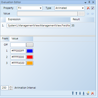
The Fill color of a rectangle should be depicted as follows:
- Blue if the temperature is below -20
- Red if the temperature of the water is 40 or above 40.
- Orange for any other temperature.
The design value of the rectangle is set to Orange.
Result
If none of the conditions is true, the design value, Orange, is taken. Optionally, a third color condition can be specified if the design color should be different from the default animated color. This could be relevant for the preview.
Discrete Example II
You want to change the background color of an analog object depending on the value of data point 2 (dp2).
- The first Condition is set to &1, and the Value is set to the Red.
- The second Condition is set to & 2A and the Value is set to Green.
Result
According to these conditions, the background color of the data point changes as follows:
- Red, if the first bit is set to 1, and when the actual value of dp2 is 1, 3, or any other odd number, the condition is true.
- Green, if the bits 2, 4, and 6 are set to 1. Therefore, when the actual value of dp2 is 42, 46, 254, or any value whose binary codes have the 2nd, 4th, and 6th bit set to 1, the condition is true.
- If neither condition is =True, the background color is by default the design value.
Examples of how the Linear Evaluation can be used:
Example 1
- The fill color of a rectangle is used to reflect the current water temperature. You can enable the Auto Range check box, and set the minimum and maximum temperature in Expression field. The fill color is set to dark blue to represent cold water (-50) and to light blue to represent a normal water (100) temperature. The Auto Range check box is enabled for this scenario. The fill color changes according to the set temperature range.
Example 2
The scenario is the same as in Example 1 but the Auto Range is disabled, and a rate is set to 10…30. The rectangle fill color is dark blue for any expression values below 10 and light blue for any values above 30.
Example 3
The scenario is the same as in Example 1 but Auto Range is disabled. The minimum range is set to 20; the maximum range is left empty. If either the Min or Max condition value is empty, the corresponding minimum or maximum range is taken from the Expression range. If the expression does not have a range, the values -1.79E+308 (Min) or +1.79E+308 (Max) are used.
The property, Stroke Dash Cap, depends on three digital data points. The following conditions are set:
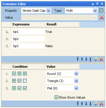
- In the first condition, if the expressions result for the digital data point BP1 is =True, then data point BP2 and BP3 are ignored and the Round attribute is applied to the property Stroke Dash Cap.
- In the second condition, if the expressions result for the digital data point BP2 and BP3 are =True, the Flat attribute is applied to the property Stroke Dash Cap.
- In the third condition, if the expression result for the digital data point BP2 is =True and data point BP3 is =False, the Triangle attribute is applied to the property Stroke Dash Cap.
- A fourth condition with all check boxes set to unspecified could also have been added.
- If the expression value results in any other combination, the condition automatically applies the default value of the Stroke Dash Cap.