Changing Object Model
This section provides instructions on creating or customizing Object Models.
For general information on object models, see the reference section.
Prerequisites:
- System Manager is in Engineering mode.
- System Browser is in Management View.
An object model created by Headquarter can be customized depending on the allowed Customization Levels (Region, Country, or Project). A copy of the selected object is created in the corresponding customization level.
Create a Customized Object Model
- You are authorized to handle libraries for a specific customization level.
- Select Project > System Settings > Libraries > L1-Headquarter > BA > Device > [Subsystem] > Object Model.
- Select the desired object model.
- Click the Models & Function tab.
- Click Customize Function
 .
.
- A confirmation message is displayed.
- Click OK.
- An object model is created in the corresponding customization level.
- Edit the object model as needed.
- Click Save
 .
.
Configure a Customized Object Model
- In System Browser, select an Object Model (data point).
- In the Configurator tab, open the Properties expander.
- Select the corresponding property.
- Drag-and-drop the property to the desired location.
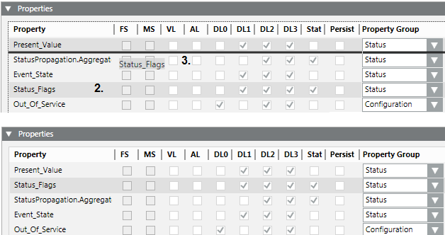
- Repeat the process for all properties to be moved.
- Click Save .

NOTE:
You can reset an edited sequence to the default setting in the menu that displays on right-click.
- Select an Object Model (data point).
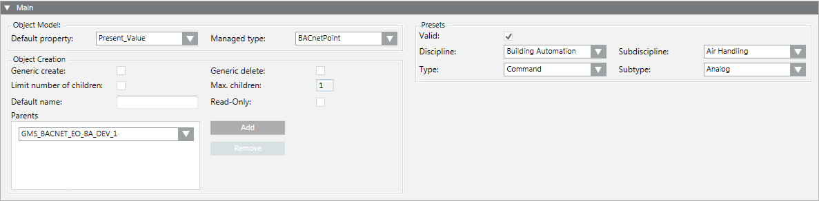
- In the Configurator tab, open the Main expander.
Configure an Object Model
- Select a default property to be used for this type of object from Default Property.
- Select a type from Managed Type to ensure that the correct application for this type is selected.
- Click Save .

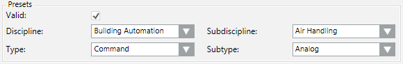
Define Presets
- Select an option in Discipline.
- Select an option in Subdiscipline.
- Select an option in Type.
- Select an option in Subtype.
- Select the Valid check box.
- Click Save .
NOTE 1:
Entries in Presets are taken over as the basic setting for Functions and instances.
NOTE 2:
Select the settings as per your search criteria.
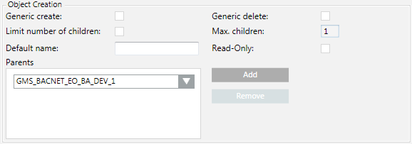
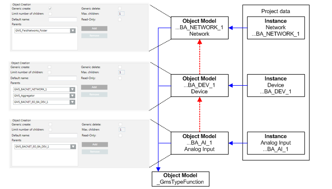
Define Object Creation
- Click Add.
- In the drop-down list, select a parent element.
- Repeat steps 1 and 2 for additional parent elements.
- Select or clear the Generic create and Generic delete check boxes.
NOTE: Permits the creation or deletion of an object in the Object Configurator.
- Select or clear the Limit number of children check box. You must also define the limits for an activated check box (unchecked = unlimited).
- Enter as needed a Default name.
NOTE: This default name is taken over when creating a child object.
- Check or clear the Read-Only check box.
NOTE: Active = Default name cannot be edited for a child object.
- Click Save .
NOTE 1:
The corresponding parents must always be defined for the given Object Model.
NOTE 2:
Recursion from the same Object Model is possible.
NOTE 3:
The Object Model aggregator is required in the views as hierarchy object and should therefore be added for most cases.
- An Object Model is selected in System Browser.
- The Properties expander opens.
NOTE: A data type of an existing Object Model is highlighted in red in the Property expander if it is not changed using the Models & Function editor. Save the Object Model to refresh the instances using the default value of the newly selected data type.
- The properties are defined in the Main expander.
- Logging data values: Select the VL check box if you want to save this property for a change of value.
NOTE: Trending data can impair your network communications.
- Logging events: Select the AL check box if you want to save this property for a change of value.
- Select the DL0, DL1, DL2, and DL3 check boxes to configure the viewer display (examples for dialog boxes: see Properties Expander).
- DL0 (Configuration: BACnet Configurator).
- DL1 (Reduced: Status and Commands window in graphic).
- DL2 (Standard: Operation).
- DL3 (Details: Extended operation).
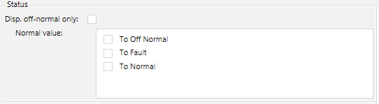
- Select the Status check box if you only intend to display the off-normal state (the function is defined in the Details expander).
- Select the Persist check box if you only intend to save the property value to have such value immediately available after a system restart.
- In the Property Group, select an option for the security setting:
- Status, Configuration, Diagnostic or Ownership.
- Repeat steps 2 to 6 for each property.
- Click Save .
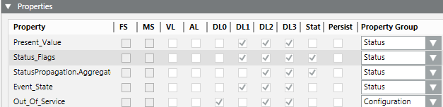
NOTE:
The FS (field system alarm) and MS (Management Station alarm) check boxes cannot be selected here.
- An Object Model is selected in System Browser.
- The Details expander is open.
- The properties are defined in the Main and Properties expander.
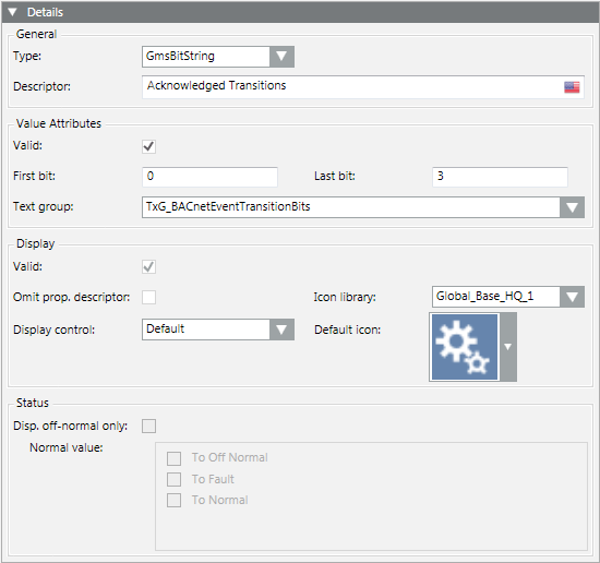
- Select the first property entry from the Property list.
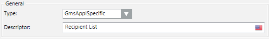
- In the General section, define the Type and enter a Description.
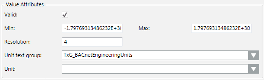
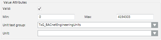
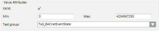
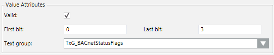
- Define the data point attributes under Value Attributes and select the text group.
- Define the view response under Display.
- Define the off-normal status under Status.
NOTE: You can define the status only if Status is selected in the Properties expander.
- Repeat the steps for all properties.
- Click Save .
- The Details expander is configured.
NOTE 1:
Properties dependent on data type are removed if the data type is changed on an existing Object Model using the Models & Function editor. This affects the Alarm Configuration, Function, and the applicable instances. The objects must be post-processed to function correctly.
NOTE 2:
A data type on an existing Object Model is highlighted in red in the Property expander if it is not changed using the Models & Function editor. Save the Object Model to refresh the instances using the default value of the newly selected data type.
Configure Value Attributes
- Select Project > System Settings > Libraries > L1-Headquarter > BA > [Subsystem library] > Functions.
- Select the Models & Functions tab.
- Open the Details expander.
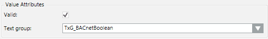
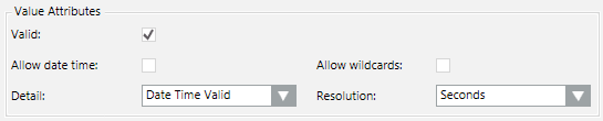
- Define the properties in the Value Attributes group box.
- Select the option for the corresponding data type under Type. Select whenever possible a data type using Gms.
- GmsBool
- GmsReal
- GmsUint
- GmsEnum
- Gms BitString
- GmsDateTime
- GmsApplSpecific
- Define data point properties.
- Select the text group. New or updated text groups must be refreshed by pressing the F5 key.
- Click Save .
NOTE:
It is possible that not all attributes of non-GMS data types are saved to the data base during data import.
Configure Display
- Select Project > System Settings > Libraries > L1-Headquarter > BA > [subsystem library] > Functions.
- Select the Models & Functions tab.
- Open the Details expander.
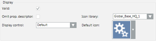
- In the Display group box, define the properties.
- Select an option at the Omit prop.descriptor check box.
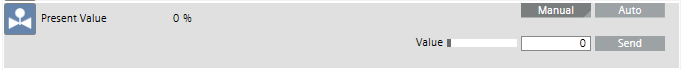
Cleared: Description, for example displays a description such as Present Value after the symbol.
Selected: The value is not displayed.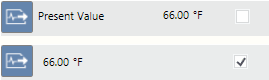
- Select the Display Control as per the selected data type.
- Default

- Priority Array

- Event Time Stamp

- Select the appropriate library under Icon Library.
- Select the icon under Default Icon. The selected icon is displayed in the viewers with the given property.
NOTE: The icon is overwritten if an icon is defined in the Enumeration or Boolean text group.
- Click Save .
Configure Status
- Select Project > System Settings > Libraries > L1-Headquarter > BA > [Subsystem library] > Functions.
- Select the Models & Functions tab.
- Open the Details expander.
- Define the properties in the Status group box.
- Select the check box in the Properties expander.
- Select Disp. Offnormal only.
- Normal status is not displayed when selected.
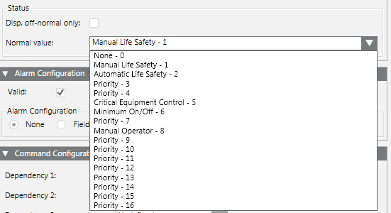
- Define the off-normal value as per your data type (GmsReal, GmsBitString, GmsEnum).
- Click Save .
GmsReal

Gms BitString
GmsEnum
Alarming on the management platform requires an engineered project and should only be used as an exception. Wherever possible, define alarming on the automation station.
NOTE:
Management station alarms cannot be forwarded if the management platform is not online.
The following alarm priorities are available:
- Life Safety
- Alarm
- Supervision
- General
- Maintenance
- Trouble
- Fault
- Status
Set up Digital Alarms
- You have selected a data point in System Browser and a corresponding Boolean property.
- The Boolean text group is assigned to a property.
- Open the Alarm Configuration expander.
- In the Alarm Configuration expander, select the Valid check box.
- Select the Management Station option.
- The alarm table opens.
- Select the Discrete or Continuous alarm kinds and continue using the appropriate work steps.
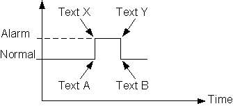
Create a Discrete Digital Alarm
The diagram displays the change in status used to issue the corresponding text.
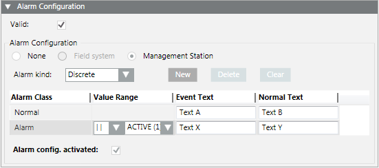
- From the Alarm kind drop-down list, select Discrete.
- In the Normal row, enter texts for Event Text and Normal Text.
- In the second row, from the drop-down list, select the status, for example Alarm.
a. In the Value Range column, select the operand and the related state.
b. Type the texts for Event Text and Normal Text.
- Select the Alarm config. activated check box.
- The Boolean alarm is created on the management platform. The corresponding MS check box is selected in the Properties overview.
- Click Save .
Create a Continuous Digital Alarm
The diagram displays the change in status used to issue the corresponding text.
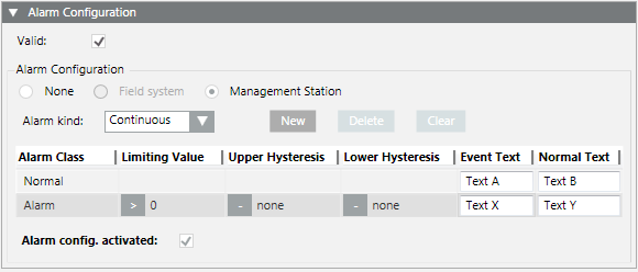
From the Alarm kind drop-down list, select Continuous.
- In the Normal row, enter texts for Event Text and Normal Text.
- In the second row, from the drop-down list, select the status, for example Alarm.
a. In the Limiting Value column, select the operand and the related state.
b. Type the texts for Event Text and Normal Text.
c. (Optional)Type an Upper and Lower Hysteresis.
- Select the Alarm config. activated check box.
- The Boolean alarm is created on the management station. The corresponding MS check box is selected in the Properties overview.
- Click Save .
Set up Analog Alarms
- You have selected a data point in System Browser and a corresponding analog property.
- Open the Alarm Configuration expander.
- In the Alarm Configuration expander, select the Valid check box.
- Select the Management Station option.
- Click New.
- A new line is added to the table.
- In the Alarm Class drop-down list, select the status.
- In the Normal row, enter texts for Event Text and Normal Text.
- In the second row, from the drop-down list, select the status, for example Alarm.
a. In the Value Range column, select the operand and the related values.
b. Enter the texts for Event Text and Normal Text.
- Repeat the appropriate entries for each state.
- Select the Alarm config. activated check box.
- The analog alarm is created on the management platform. The corresponding MS check box is selected in the Properties overview.
- Click Save .
- An Object Model is selected in System Browser.
- The Properties expander and the Alarm Configuration expander are opened.
- The properties were defined in the Main and Properties expander.
- In the Properties expander, select the property (for example, Alarm, Fault).
- In the Alarm Configuration expander, select the Valid check box.
- Select the Field system option.
- In the Reference to Alarm table, select the corresponding alarm table.
- Repeat steps 1 to 4 for each property as needed.
- Click Save .
- Displays the Alarm Configuration expander.
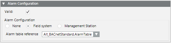
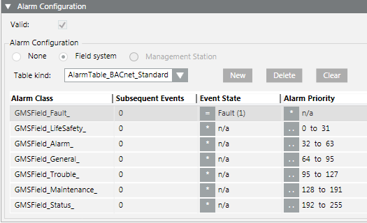
Example of an alarm table.
The functionality must be defined to operate properties. This may range from a simple Off/On to more complex functions to operate priority arrays for the various data types. For background information, see the Object Model Editor section.
NOTE:
For a list of available commands, see the Command List section.
Boolean (Out of Service)
- You have selected a data point in System Browser and a corresponding Out of Service property.
- Open the Command Configuration expander.
- Under Dependency 1, select the option Out_of_Service.
- Click New.
- A new line is added to the table.
- In the Command column, select status BACnetWriteToggleOn.
- In the Label column, enter a designation, for example, Out of Svc for the button.
- In the Out_of_Service column, first select the operand equal sign (=) and then select the option In Service.
- Select Alias.
- Repeat steps 4 to 7 as per the table below.
- The Out of Service property is configured.
- The buttons for operation are defined.
Command | Label | Acked_Transitions | Alias | |
BACnetWriteToggleOn | Out of Service | = | In Service | n/a |
BACnetWriteToggleOff | In Service | = | Out of Service | n/a |
NOTE:
Additional dependencies can be defined as needed. In this case, select Dependency 2 and 3 and configure the appropriate response.
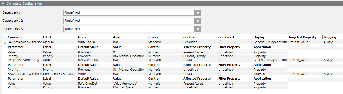
Analog Output (Present Value)
- You have selected an analog output in System Browser and a corresponding Present Value.
- Open the Command Configuration expander.
- Under Dependency 1, select option Undefined.
- Click New.
- A new line is added to the table.
- In the Command column, select status BACnetAnalogWithPriority.
- In the Label column, enter a designation, for example, Command for the buttons.
- In the Current_priority column, first select the operand and then select the desired options as needed.
- Select Alias.
- Define the user group (Standard, Event, Advanced, Ownership) used to execute the function.
- Repeat steps 3 and 4 as per the table below.
- The Present Value property is configured.
- The buttons for operation are defined.
Command | Label | Acked_ Transitions | Alias | Group | Expander | Combi-ned | |
BACnetAnalogWithPriority | Command | * | n/a | n/a | Standard | Expander |
|
BACnetReleaseWithPriority | Release | * | n/a | n/a | Standard | Expander |
|

Detailed Information on BACnetAnalogWithPriority | |||||
Parameter | Label | Default Value | Value | Control | Affected property |
Value | Value | Runtime | [x] | Numeric | Present_Value |
Priority | Priority | Provided | MO =8 | DropDown | Undefined |
- You have selected an Object Model or Function in System Browser.
- The Symbols expander is open.
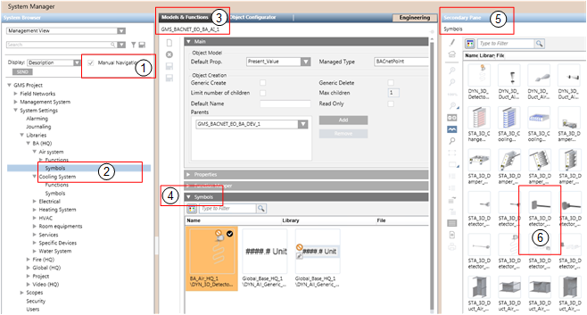
- In System Browser, select the Manual Navigation check box.
- Select Project > System Settings > Libraries > L1-Headquarter > BA > [subsystem library] > [object model or function].
- Select the Models & Functions tab.
- Open the Symbols expander.
- Select the corresponding Symbols library.
- Right-click the symbol library and select the Secondary pane.
- The Secondary pane opens and displays available symbols.
- Select the desired symbol and drag-and-drop it to the Symbols expander (left-click and hold).
- Repeat step 7 for all symbols you want to assign to this Object Model or Function.
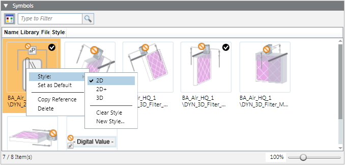
- To define the library style, right-click the desired symbol and select Style: > 2D, 2D+ or 3D.
- To define the default symbol for each library style, right-click the desired symbol and select Set as Default.
- Click Save .
- The symbols are assigned to the Object Model or Function.
- The library style is defined for each symbol.
- The default symbol for each library style is defined.
NOTE:
During graphics engineering, the symbol designated as the default symbol is dragged-and-dropped to a data point where the graphic is placed.
- You have selected an Object Model or Function in System Browser.
- Select Project > System Settings > Libraries > L1-Headquarter > BA > [subsystem library] > [object model or function].
- Select the Models & Functions tab.
- Open the Symbols expander.
- Select the symbol for deletion.
- Right-click the symbol and select Delete.
- Click Save .
- The symbol is deleted.
- Select the Manual Navigation check box.
- Select Project > System Settings > Libraries and select an Object Model or Function.
- Open the Graphic Templates expander.
- Select the graphic template for deletion.
- Right-click the graphic template and select Delete.
- Click Save .
- The graphic template is deleted.
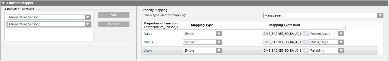
You must use the Function Mapper to assign all Functions associated with an Object Model. As a result, you must assign a Function, for example, Temperature sensor, humidity sensor, air quality sensor, and so on to an analog input of System 1. This assignment must also be carried out for Systems 2 and 3.
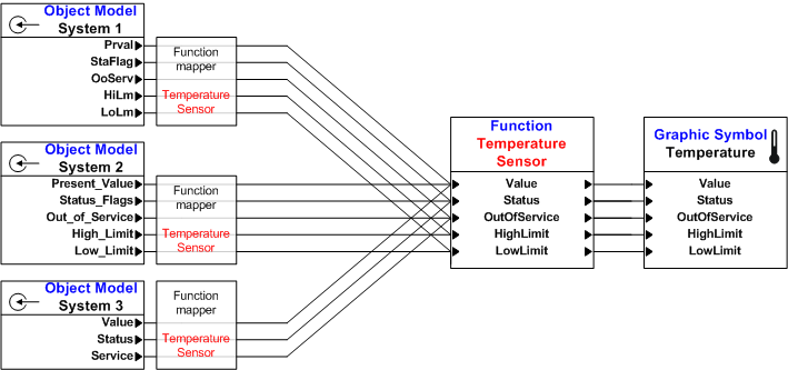
- The corresponding Functions are created and configured.
- The appropriate Object Model is selected.
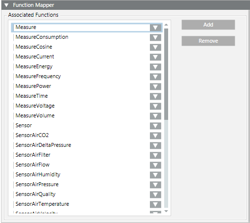
- Open the Function Mapper expander.
- Click Add.
- In the Associated Functions list, select the corresponding Function.
- Select the mapping view for View type used for mapping.
NOTE: Always use the same mapping view within a system. Otherwise, you may not be able to map the objects.
- In the Mapping Type column, select one of the Functions (see also Mapping a Function to an Object Model):
- Simple (Function properties mapping to Object Model properties)
- Functional (mapping children together with Functions)
- Extended (mapping children together with path and Object Model properties)
- Mixed (mapping children together with path and Functions)
- In the Mapping Expression column, select the appropriate attribute.
- Repeat steps 2 to 6 for all Functions you want to assign to this Object Model.
- Click Save .
- The Function Mapper is configured.
NOTE:
A selected Function can be assigned by System Browser to the Associated Functions box via drag-and-drop.
Each object is assigned to a text catalog with the corresponding texts. Check the text catalog for the text contents to ensure that proper information is displayed when the state of a data point changes. New or updated text groups must be refreshed by pressing the F5 key.
- Select Project > System Settings > Libraries and select an Object Model or Function.
- Click the Models & Function tab.
- In the Properties expander, select the property (for example, Present_Value).
- In the Details expander, double-click Unit text group.
- The corresponding text group is selected in System Browser.
- Select the Text Group Editor tab.
- The entries for the selected text group are displayed.
To process instances, it is helpful to be able to easily locate the corresponding Function or Object Model in System Browser.
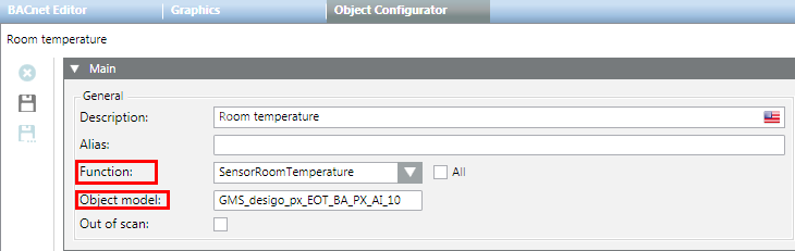
- Select Project > System Settings > Libraries and select an Object Model or Function.
- Select the Object Configurator tab.
- In the Main expander, select the General text field.
- Double-click the Function or Object model description.
- The corresponding Function or Object Model is selected and displayed in System Browser.
- Click the Models & Function tab.
- The corresponding Function or Object Model is displayed.